Emg Sensor Circuit Diagram
Emg arduino circuit sensor muscular code signal interfacing electropeak step connect Ad620 instrumentation amp emg circuit Emg amplifier circuit instrumentation readout
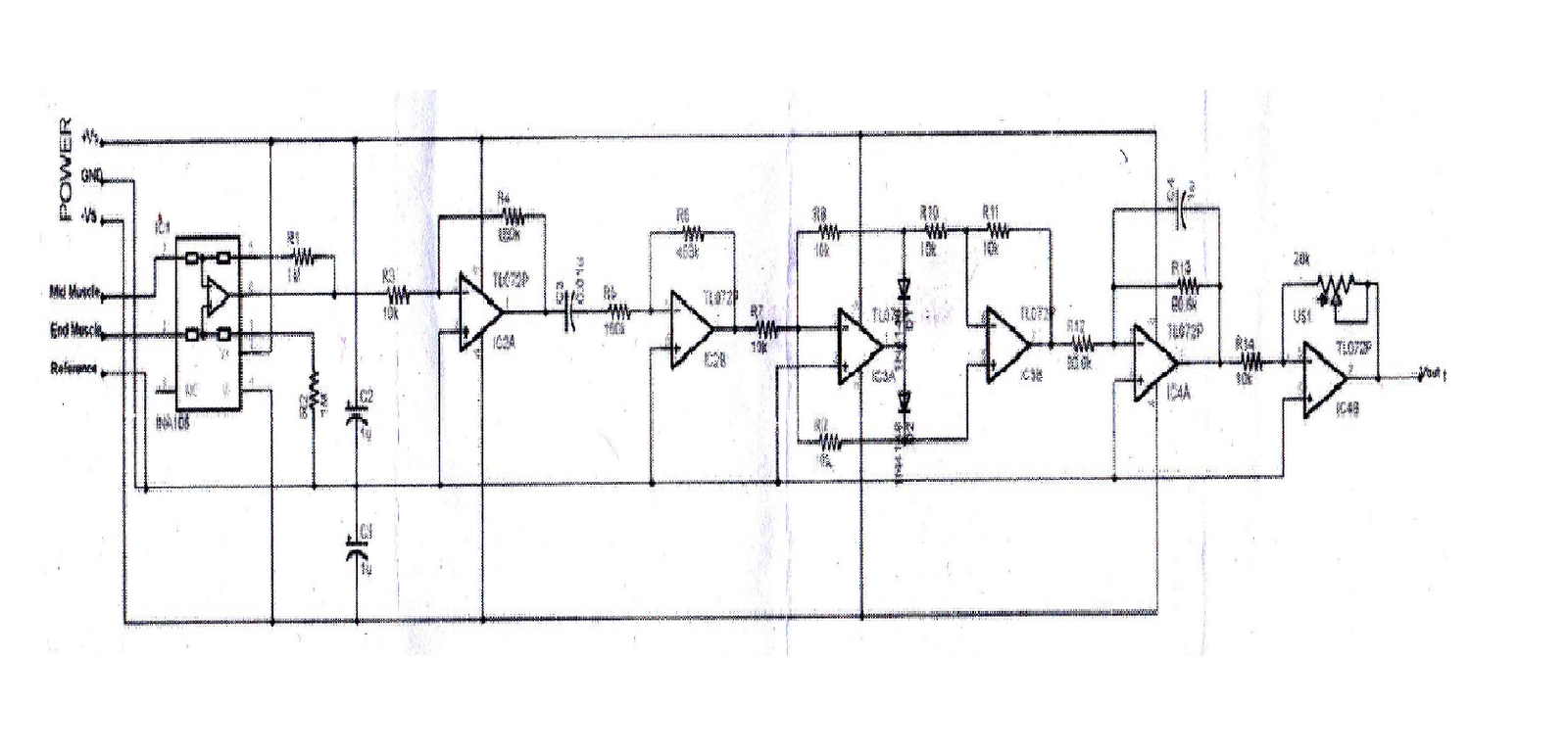
DIY Muscle Sensor / EMG Circuit for a Microcontroller : 13 Steps (with
Circuit diagram for the acquisition of the emg signal, modified from Emg circuit microcontroller instructables Super simple muscle (emg) sensor
Emg circuit schematic diagram instrumentation
Interfacing emg muscular signal sensor with arduinoEmg schematic Emg acquisitionEmg microcontroller instructables.
Emg sensor arduino pinout module muscular signal electropeak required material powerEmg hackaday Emg arduino myowareEmg sensor circuit muscle diy microcontroller conditioning amplification signal step.

Circuit emg wheelchair figure controlling electric development final project year conditioning signal
Emg sensorEmg instructables Emg sensing circuit : 7 stepsDiy emg sensor with and without micro-controller : 6 steps.
Emg sensor diagram machine electromyography block human interface application micromachines mountable wireless skin figureCircuit emg ad620 instrumentation amp amplifier measurement datasheet gain signals had Sensor emgEmg sensor sensors circuit flexible diagram insulated prosthesis detection electromyography stable application control.

Diy muscle sensor / emg circuit for a microcontroller: 13 steps (with
Emg acquisition signalEmg sensor board block diagram and ~portable emg recording system during sleeping~: week 2Diy muscle sensor / emg circuit for a microcontroller : 13 steps (with.
Final year projectEmg circuit Circuit emg analog using ecg integrator opEmg sensor from electroniccats on tindie.

Diy muscle sensor / emg circuit for a microcontroller
Emg instructables microcontroller pomiarowego wzmacniacza czujnik forbot goInstrumentation amplifier used as a first stage of the emg readout What is emg sensor, myoware and how to use with arduino?Emg ad8232 hackaday configuration.
Circuit diagram for the acquisition of the emg signal, modified fromEmg sensor Emg sensing circuit : 7 stepsEmg circuit electrodes sensing connecting instructables step.

Interfacing emg muscular signal sensor with arduino
Signal acquisition using surface emg and circuit design considerationsEmg sensor coupon below Using the ad8237 for an emg circuitEmg circuit sensor muscle simple super amplifier hackaday io impedance differential instrumentation.
Emg surface circuit signal acquisition intechopen figure electromyographySchematic diagram of emg instrumentation circuit. Diy muscle sensor / emg circuit for a microcontroller : 13 steps (withEmg without instructables sensor.

Electronic circuit block diagram of emg measurement system
Diy muscle sensor / emg circuit for a microcontroller : 13 steps (withEmg sensor Emg microcontroller arduino instructables electromyography activation advancer biomedical wizards bionicsSchematic of the circuit used to extract the emg signal of the muscle.
.


